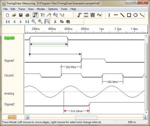
Diagrams uml draw
Table of Contents
Table of Contents
Are you struggling with drawing timing diagram in Visio? Do you find it confusing and challenging to create accurate diagrams? Keep reading to learn the ins and outs of how to draw timing diagram in Visio and make your diagram creation process easier!
Pain Points of Drawing Timing Diagram in Visio
Creating an accurate and efficient timing diagram in Visio can be a challenging task, especially for those who are new to the software. The process requires a lot of attention to detail, carefulness in placing symbols and lines, and a clear understanding of the software features. If you’re not familiar with Visio’s timing diagram features and tools, you may find that you’re spending longer than necessary on creating your diagram.
How to Draw Timing Diagram in Visio
Visio offers a specific timeline and sequencing shapes, built to create timing diagrams with ease. These shapes have many types of interactions which can be used in waveform diagrams. Follow the below steps to create a timing diagram in Visio:
- Open Visio and select “Timeline” under the “Category” section.
- Select “Basic Timeline” and drag it onto the workspace area.
- Add additional shapes such as “Waveform,” “Trigger,” and “Data Flow” etc. from the “Timing” stencil to the workspace.
- Add events to the timing shapes by right-clicking on the shape and selecting “Add Event.”
- Connect the events in the order they will occur using the “Connector” tool.
- Remember to label each shape and connector to indicate what they represent in the diagram.
By following these steps, you can create your timing diagrams in Visio with ease, speed, and efficiency.
The Importance of Timing Diagrams
Timing diagrams are essential in digital electronics and have several uses. These diagrams can help analyze the timing behavior of digital signals in complex digital circuits when the activities occur at high frequency. Utilizing timing diagrams can help identify glitch potential, verify the relationship between inputs and outputs, analyze the edge effects on the circuits, and more.
The use of Timing Diagrams in Different Industries
Timing diagrams have several applications in different industries, including aerospace and defense, medical equipment, telecommunications, and electronics industries. These diagrams can be useful for wiring schematics, signal timing analysis, and the identification of circuits problems in different devices.
Personal Experience with Drawing Timing Diagram in Visio
As an electronic design engineer, I have used timing diagrams in Visio to create diagrams that help me and my team understand the behavior of digital signals. While there can be a learning curve to get started with the software, the built-in shapes, objects, and connectors make it easier to create useful and efficient diagrams. By using Visio, I have saved time and can easily communicate changes and improvements to the team.
Question and Answer about Drawing Timing Diagram in Visio
Q: Can I import data into Visio to create my timing diagram?
A: Yes, Visio has an import feature that allows you to import data from Excel or CSV files into your diagram.
Q: Can I add images to my timing diagram in Visio?
A: Yes, Visio allows you to add and edit images, shapes, and other objects to diagrams with ease.
Q: How do I add annotations to my timing diagram in Visio?
A: You can add comments, notes, text boxes, and other tools to annotate your timing diagram in Visio. These annotations can be used to describe the diagram’s behavior, functionality, and any other essential details.
Q: Can I customize the look of my timing diagram in Visio?
A: Yes, Visio has several formatting and design tools that allow you to customize the look and feel of your timing diagram. You can change colors, fonts, shapes, and more to create a visually appealing and informative diagram.
Conclusion of How to Draw Timing Diagram in Visio
Drawing timing diagrams in Visio can be challenging, but by following the above steps, you can create your diagrams with ease and efficiency. Timing diagrams are essential in different industries and can help identify and solve problems in different digital circuits. With Visio’s built-in tools, you can create diagrams that are easy to read and understand, improving collaboration with your team and reducing the chance of errors.
Gallery
Timing Diagram Basics — Rheingold Heavy
![]()
Photo Credit by: bing.com /
How To Draw Timing Diagram - Diagram Resource Gallery

Photo Credit by: bing.com / diagrams uml draw
Explain Visio Timing Diagram Construction - Techyv.com

Photo Credit by: bing.com / timing diagram visio waveform techyv software digital there easier resources which work make
Timing Diagram Digital Logic - Digital Photos And Descriptions

Photo Credit by: bing.com / timing logic doentation
All You Need To Know About SoC Design, Methodologies And Techniques
Photo Credit by: bing.com / timing diagram drawing tool tools diagrams example font


